Exit Deck | Component 3 • Studio Effects
Component 3 Overview

Studio Effects: Time-Based vs. Modulation Processing

Studio effects shape space, depth, timbre, and motion. In Component 3, effects are divided into Time-Based (Delay, Reverb) routed via Aux Sends, and Modulation (Chorus, Phaser, Flanger) routed as Serial Inserts.

Landmark Audio Recording Modulation & Time Effects Compared
YouTube ↗
Phaser vs. Flanger vs. Chorus vs. Vibrato Explained
Audio Engineering Demonstration
A-Level Component 3 Critical Ear-Training Benchmark
Ear-Training Diagnostic: The Micro-Time Continuum
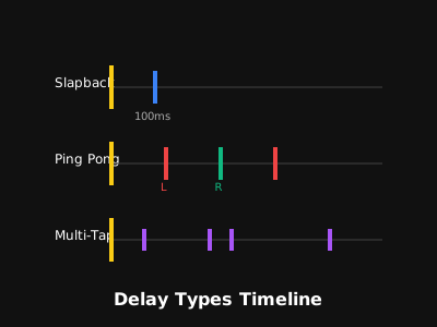
  • Understand the delay time spectrum: Phase shifting uses no audible delay (0ms) but phase-shifts all-pass filters; Flanging uses ultra-short 1-15ms delays creating harmonically related comb notches; Chorus uses 15-35ms delays with LFO pitch detuning; and Echo/Delay uses 50ms to 1000ms+ for distinct rhythmic repeats.
  • Notice how reverb is simply thousands of micro-delays reflecting so densely that individual echoes blur into a continuous acoustic decay tail.
Aux Send / ReturnSerial InsertWet/Dry BalanceComb FilteringTime Spectrum
Architecture & Physics Studio Signal Routing Architecture
Delay & Modulation Timeline Diagram
🎛️ The 5 Core Studio Effects
Inserts (Phaser / Flanger) vs. Parallel Aux Sends (Delay / Reverb)
Insert Processing vs. Auxiliary Send/Return Routing

In the exam, examiners test your understanding of signal routing: (1) Insert Routing: 100% of the channel audio passes directly through the processor (ideal for Phasers, Flangers, EQs, and Compressors to alter the entire timbre).

(2) Aux Send / Return (Parallel): A portion of the dry signal is tapped off via an auxiliary send knob and sent to a shared effects bus (ideal for Reverb and Delay, keeping the original dry track punchy and uncolored).

The 4 Primary Time & Modulation Domains
1
Phase Inversion & All-Pass (<1 ms): Phase cancellations created by active RC filter stages without time delay; generates sweeping non-harmonic notches.
2
Flanger Comb Filtering (1–15 ms): Ultra-short delay line summed with dry signal creates deep harmonically spaced comb notches; LFO sweep produces jet whoosh.
3
Chorus Pitch Detuning (15–35 ms): Moderate delay line modulated by an LFO causes micro pitch-shifting (Doppler effect), simulating multiple performers.
4
Discrete Delay & Reverb (50 ms – 3000 ms+): Distinct discrete audible repetitions (Echo/Slapback) or infinite diffuse reflections simulating physical room acoustic decay.
Time-Based Processing

Delay & Echo: Tape Loops, BBD & Dotted 8ths

Delay captures an audio signal and reproduces it after a set duration. From Sam Phillips' 1950s tape slapback to The Edge's tempo-synced dotted eighth notes, delay defines rhythmic drive and spatial depth.

Landmark Audio Recording The Masterclass in Dotted Eighth Delay
YouTube ↗
"Where The Streets Have No Name" (1987 • Korg SDD-3000)
U2 (The Edge)
A-Level Component 3 Critical Ear-Training Benchmark
Ear-Training Diagnostic: Rhythmic Subdivision & Stereo Bouncing
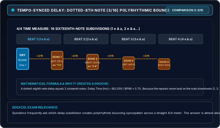
  • Listen to The Edge's iconic chiming Stratocaster riff: he plays straight eighth notes, but the delay unit generates a dotted-eighth repeat (3/16 note, approx 360ms at 125 BPM) mixed equally with the dry signal, creating a cascading sixteenth-note continuous rhythmic gallop.
  • Notice the tone of the repeats: analog BBD and tape delay units roll off high frequencies with each successive repeat (damping), preventing the echoes from cluttering the lead vocal or rhythm section.
Tape SlapbackDotted 8th NoteFeedback LoopAnalog BBDPing-Pong Delay
Architecture & Physics Delay Signal Architecture
Dotted Eighth Note Delay Rhythm Diagram
🔁 Delay & Echo Technologies (1950s–Present)
Tape Loop (Space Echo) • Analog BBD • Digital Tempo-Sync Multi-Tap
From Reel-to-Reel Tape to Digital Rhythmic Subdivision

Early delay was purely electro-mechanical: tape echo units (Watkins Copicat, Roland RE-201 Space Echo, Maestro Echoplex) ran a continuous loop of magnetic tape past multiple playback heads. Motor speed governed delay time, while wow & flutter introduced warm organic modulation.

In the 1970s, Bucket Brigade Device (BBD) analog chips eliminated moving mechanical tape, passing electrical charges across capacitor buckets. In the 1980s, digital delays (Korg SDD-3000, TC Electronic 2290) allowed millisecond-accurate tempo synchronization.

Key Delay Parameters & Formulas (Exam Essential)
1
Delay Time & Tempo Sync Formula: Duration between dry sound and repeat. Dotted-eighth formula: (60,000 / BPM) x 0.75 ms. At 120 BPM, quarter = 500ms; dotted eighth = 375ms.
2
Feedback (Regeneration): Routes a percentage of the output back into the delay line. 0% = single slapback repeat; 50% = 4-5 repeats; 100%+ = runaway analog self-oscillation.
3
High-Frequency Damping: A low-pass filter inside the feedback loop attenuates treble on each successive repeat, mimicking natural acoustic reflection dissipation in air.
4
Ping-Pong & Multi-Tap Panning: Alternates echoes hard left and hard right across the stereo field, providing massive spatial width without masking the center mono vocal.
Acoustic & Digital Space

Reverb Effects: Chambers, Plates & Gated Snare

Reverberation simulates acoustic boundary reflections. Spanning natural basement chambers, 600lb EMT 140 steel plates, Fender tube springs, Lexicon digital algorithms, and Phil Collins' explosive 1980s gated snare.

Landmark Audio Recording The Defining Gated Reverb Drum Sound
YouTube ↗
"In The Air Tonight" (1981 • Townhouse Stone Room & SSL)
Phil Collins
A-Level Component 3 Critical Ear-Training Benchmark
Ear-Training Diagnostic: Gated Decay vs. Natural RT60 Decay
  • Listen to Phil Collins' legendary drum fill at 3:41: the snare and toms explode into a massive, cavernous stone room ambient tail that is violently and unnaturally chopped off into dead silence by an SSL noise gate.
  • In contrast, listen to natural acoustic chamber or plate reverb: early reflections arrive within 5-30ms, followed by a dense, smooth exponential decay that fades linearly over several seconds according to its RT60 time.
RT60 Decay TimeEMT 140 PlateGated ReverbPre-Delay GapConvolution IR
Architecture & Physics Reverb Physical Mechanics
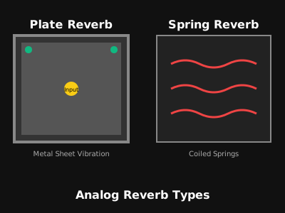
Reverb Plate and Spring Transducer Diagram
🏛️ The 5 Reverb Generations
Acoustic Chamber • EMT 140 Plate • Spring • Lexicon Algorithmic • Convolution IR
The Evolution of Artificial Reverberation

Before digital processors, studios used dedicated physical spaces: acoustic echo chambers (tiled basement rooms with a speaker and mic). In 1957, EMT introduced the EMT 140 Plate Reverb—a 1x2 meter cold-rolled steel sheet suspended on springs, vibrating via an electromagnetic driver.

Fender pioneered built-in spring reverb tanks in guitar amps (Twin Reverb). In 1978, Lexicon 224 and EMT 250 introduced microprocessor-based algorithmic digital reverb. Today, convolution reverb captures real physical acoustics using Impulse Responses (IRs).

Key Reverb Parameters & Engineering (Exam Essential)
1
RT60 (Reverberation Time 60 dB): The time in seconds required for sound pressure reflections to decay by 60 dB below the direct sound. Small room = 0.5s; Concert Hall = 2.0s–3.0s.
2
Pre-Delay (The Distance Offset): The gap in milliseconds (10–60ms) between the dry sound and the onset of early reflections. Preserves upfront vocal presence and clarity before wash begins.
3
Diffusion & High-Frequency Damping: Diffusion controls reflection density; damping filters out high frequencies faster, simulating soft furnishing and human air absorption.
4
Gated Reverb Signal Chain: Snare Drum → Massive Non-Linear Chamber/Plate → Aggressive VCA Compressor → Noise Gate with Fast Release (Hold ~200ms, Release 10ms).
Modulation Processing

Chorus Effect: BBD Micro-Delay & Stereo Width

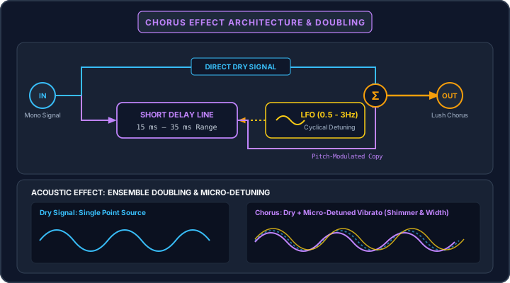
By splitting the signal, delaying one path by 15–35ms, and constantly modulating its pitch with an LFO, chorus simulates the natural pitch and timing discrepancies of multiple instruments playing in unison.

Landmark Audio Recording The Lush Watery Grunge Guitar Tone
YouTube ↗
"Come As You Are" (Nevermind • 1991 • Butch Vig)
Nirvana (Kurt Cobain)
A-Level Component 3 Critical Ear-Training Benchmark
Ear-Training Diagnostic: Pitch Detuning & Dimensional Movement
  • Listen to Kurt Cobain's opening D-string guitar riff: recorded with an Electro-Harmonix Small Clone analog chorus pedal, the guitar sounds submerged, watery, and lush. The pitch continually wobbles subtly sharp and flat.
  • Listen to the stereo width: in dual-voice and stereo chorus units (like the Roland Dimension D or JC-120), the dry signal is sent to one channel and the pitch-vibrato signal to the opposite channel, expanding the stereo field far beyond the physical speakers.
Analog BBD15–35ms DelayLFO ModulationRoland Dimension DPitch Detuning
Architecture & Physics Chorus Architecture & Circuitry
Chorus Modulation Signal Flow
🌊 Analog BBD Chorus Circuits (1975–Present)
Bucket Brigade Device • Low-Frequency Oscillator (LFO) • Pitch Detuning
From Unison Vocal Doubling to Synth Staple

Vocalists singing in unison never sing at the exact same pitch or millisecond; their slight micro-variations create acoustic beating and richness. Chorus pedals were invented to replicate this electronically using analog BBD delay chips (MN3007).

Roland integrated this into the JC-120 amplifier (1975), the CE-1 pedal (1976), and the legendary Juno-6/60/106 synthesizers, turning thin single-oscillator analog voices into massive, cinematic polyphonic stereo pads.

How Chorus Transduction Works (Exam Essential)
1
The 15–35 ms Delay Window: Delay times below 15ms cause comb filtering (flanging); delay times above 35ms produce distinct slapback echoes. 15–35ms is the optimal Haas perceptual doubling zone.
2
LFO Frequency Modulation (Doppler Pitch Shift): A Low Frequency Oscillator (0.1 Hz – 5 Hz) modulates delay clock speed. As delay shortens, pitch rises sharp; as delay lengthens, pitch drops flat.
3
Summing & Acoustic Phase Beating: Combining the unmodulated dry signal with the pitch-modulated wet signal creates continuous phase interference and rich acoustic chorusing.
4
Key Parameters: Rate & Depth: Rate (Speed) controls LFO cycle frequency in Hertz; Depth (Width) controls the amount of pitch detuning in cents.
Modulation Processing

Phaser Effect: All-Pass Filters & Sweeping Notches

Unlike delay-based effects, phasers use non-linear all-pass filter stages to shift the phase of specific frequencies. When blended with the dry signal, they create sweeping non-harmonically spaced notches.

Landmark Audio Recording The Brown Sound Swirl & Harmonic Bite
YouTube ↗
"Ain't Talkin' 'Bout Love" (1978 • Sunset Sound)
Van Halen (Eddie Van Halen)
A-Level Component 3 Critical Ear-Training Benchmark
Ear-Training Diagnostic: Non-Harmonic Sweeping Notches
  • Listen to Eddie Van Halen's arpeggiated intro riff: before hitting his Marshall Super Lead, his guitar passed through an MXR Phase 90 pedal set to a slow sweep rate. Notice the smooth, warm, liquid 'chewiness' across the frequency spectrum.
  • Compare this to flanging: a phaser does NOT sound like a metallic jet plane. Because the notches are created by electronic all-pass filters rather than a time delay, the notches are spaced non-harmonically, giving a smoother, vocal-like sweep.
MXR Phase 90All-Pass FiltersNon-Harmonic NotchesPhase CancellationLFO Sweep
Architecture & Physics Phaser Filter Topology
Phaser All-Pass Filter Diagram
🌀 Active All-Pass Phase Circuits (1970s–Present)
4-Stage (Phase 90) • 8-Stage (Phase 100) • Sweeping Cancellation Notches
The Engineering of Phase Cancellation Without Delay

The phaser was created in the early 1970s (MXR Phase 90, Electro-Harmonix Small Stone, Maestro PS-1) as an analog solid-state alternative to cumbersome tape flanging. Instead of using expensive, noisy delay chips, engineers used cascaded operational amplifiers configured as all-pass filters.

Each pair of all-pass filter stages introduces a 180° phase inversion at a specific frequency. When the phase-shifted signal is mixed with the original dry signal, complete destructive phase cancellation occurs at that frequency, cutting a deep notch in the frequency spectrum.

How Phaser Filtering Works (Exam Essential)
1
All-Pass Filter Stages & Notches: Each 2 stages create 1 notch: a 4-stage phaser (MXR Phase 90) produces 2 sweeping notches; an 8-stage phaser produces 4 notches; a 12-stage phaser produces 6 notches.
2
Non-Harmonic Notch Spacing: Because phase shift depends on resistance and capacitance values, the notches are spaced logarithmically/non-harmonically, creating a subtle, vocal-like sweep.
3
LFO Sweep Modulation: An LFO modulates variable resistors (JFET transistors or photocells) to sweep the notch center frequencies up and down across the audio spectrum.
4
Feedback (Resonance / Color): Feeding a portion of the phased signal back to the input deepens the notches and sharpens the resonance peaks, creating an intense, cutting swirl.
Modulation Processing

Flanger Effect: Comb Filtering & Jet Plane Sweeps

Flanging combines an audio signal with an ultra-short delayed duplicate (1–15ms). The interaction produces a dense series of harmonically related comb-filter notches that sweep across the spectrum, creating an iconic jet-plane whoosh.

Landmark Audio Recording The Galloping Jet-Plane Comb Filter
YouTube ↗
"Barracuda" (Little Queen • 1977 • Mike Flicker)
Heart (Nancy Wilson)
A-Level Component 3 Critical Ear-Training Benchmark
Ear-Training Diagnostic: Metallic Comb Notches & Hollow Jet Whoosh
  • Listen to Nancy Wilson's galloping open-E string chug: notice the pronounced metallic, hollow resonance that whooshes dramatically up and down in synchronisation with the music, mimicking the sound of an aircraft taking off.
  • Notice the harmonic comb peaks: unlike a phaser's mellow phase shifting, flanging generates dozens of mathematically precise, harmonically related notches that extend from the low-mids all the way to 20 kHz.
1–15ms DelayHarmonic Comb FilterJet-Plane WhooshTape FlangingNegative Feedback
Architecture & Physics Flanger Comb Filter Mechanics
Flanger Comb Filter Frequency Curve
✈️ Tape Flanging & Comb Filter DSP (1960s–Present)
1–15ms BBD Delay • Harmonically Related Peaks/Troughs • Tape Reel Friction
The Physical Origin of 'Flanging' on Tape Decks

Flanging originated in 1960s studios (John Lennon and Ken Townsend at Abbey Road for ADT, and George Chkiantz at Olympic Studios on The Small Faces' 'Itchycoo Park'). An engineer played two identical tape recordings simultaneously on synchronized tape decks.

By gently pressing a thumb against the metal flange (rim) of one tape reel, the friction momentarily slowed down that tape by a few milliseconds. Releasing the thumb allowed it to catch up. The resulting micro-time differential created the legendary sweeping 'jet plane' sound.

How Flanging Comb Filtering Works (Exam Essential)
1
The 1–15 ms Micro-Delay Window: At 1–15ms, the ear cannot perceive the delay as a separate echo. Instead, the delayed wave interferes with the direct wave, causing reinforcement (peaks) and cancellation (troughs).
2
Harmonically Related Comb Notches: Cancellation occurs at frequencies where delay time equals an odd half-wavelength ($f = \frac{1}{2\tau}, \frac{3}{2\tau}, \frac{5}{2\tau}...$), producing a comb-like linear harmonic series of deep notches.
3
LFO Sweep Across Spectrum: Modulating the delay time from 1ms up to 10ms moves the comb filter notches up and down the frequency spectrum continuously.
4
Positive vs. Negative Feedback: High feedback creates the intense jet resonance. Positive feedback boosts odd harmonics (hollow woody tube); negative feedback inverts the wet signal, creating an eerie, metallic bite.
Master Specification Matrix

Studio Effects: The Master Exam Matrix

The complete Edexcel Component 3 comparative reference for all 5 studio effects: time ranges, circuit topologies, notch characteristics, and signature exam traps.

Comparative Listening Comprehensive Effects Demonstration
YouTube ↗
Recognizing Studio Effects in Context • Exam Checklist
Component 3 Master Review
A-Level Component 3 Audio Recognition Guide
Ear-Training Diagnostic: Identifying Effects in Context 3 Exams
  • In Component 3 listening examinations, you must immediately recognize effects by ear: (1) Discrete rhythmic repeats = Delay, (2) Ambient acoustic decay = Reverb, (3) Shimmering detuned stereo widening = Chorus, (4) Smooth vocal-like non-metallic swirl = Phaser, (5) Aggressive metallic jet-plane hollow comb filter = Flanger.
  • Use the Master Matrix table on the right to memorize exact delay millisecond boundaries, parameter functions, and technical circuit terminology.
Top 5 Edexcel Component 3 Exam Traps
1
Phaser vs. Flanger Notch Distinction: A Flanger uses a micro time-delay (1-15ms) creating HARMONICALLY related comb filter notches. A Phaser uses all-pass filters (NO delay) creating NON-HARMONICALLY spaced notches. Do not confuse them!
2
Pre-Delay Function in Reverb: Pre-delay does NOT make the reverb decay longer. It delays the ONSET of the reverb tail, allowing the dry vocal/transient to cut through cleanly before the reflections wash over it.
3
Insert vs. Aux Routing Principles: Reverb and Delay belong on parallel Aux Send buses with 100% wet mix so multiple tracks share one room without muddying direct dry signals. Phasers and Flangers belong as channel INSERTS.
4
Chorus Time Window (15–35ms): Delays shorter than 15ms sound like flanging/filtering. Delays longer than 35ms sound like distinct slapback echo. 15–35ms is the precise sweet spot where the ear perceives doubling.
5
Tape Flanging Origin Story: Flanging was named because engineers physically pressed a finger/thumb onto the FLANGE (outer rim) of a tape supply reel to temporarily delay it by milliseconds relative to a synchronized twin tape deck.
Component 3 MatrixExam TrapsAll-Pass vs CombPre-DelayDotted 8th Math
Specification Review Studio Effects Comparison Diagram
Effects Timeline and Hierarchy Diagram
🏆 The Master Specification Matrix
5 Studio Effects • Time Delays • Circuit Physics • Signal Routing • Exam Traps
Edexcel Component 3 Examination Essentials

When answering questions on studio effects, always use precise technical terminology: 'All-pass filter stages', 'Destructive phase cancellation', 'Harmonically related comb filter series', 'Bucket Brigade Device (BBD)', 'Low Frequency Oscillator (LFO)', 'Pre-delay gap', 'RT60 decay time', and 'Auxiliary send/return parallel routing'.

Common exam questions require calculating delay times from BPM (e.g. 60,000 / BPM = quarter note delay in ms), explaining how pre-delay improves vocal clarity, or describing the physical tape technique that gave flanging its name.

Effect Delay Time Circuit Method Notch Spacing Common Routing & Exam Key
Delay & Echo 50ms to 2000ms+ Tape loop, analog BBD, digital DSP memory Discrete distinct echoes Aux Send / Return bus; sync to project BPM (dotted 8th formula).
Reverb Effects 0.5s to 5.0s+ RT60 Acoustic chamber, steel plate, spring, convolution Thousands of diffuse reflections Aux Send / Return bus; pre-delay preserves vocal intelligibility.
Chorus Effect 15ms to 35ms Analog BBD delay line + LFO pitch detuning Smooth pitch detuned spread Channel Insert or Aux; simulates multiple performers playing in unison.
Phaser Effect 0ms (No delay line) Cascaded active RC all-pass filter stages 2, 4, or 6 non-harmonic notches Channel Insert; non-harmonic spacing creates warm, vocal-like swirl.
Flanger Effect 1ms to 15ms Ultra-short BBD delay line + high feedback Dense harmonically related comb notches Channel Insert; high feedback creates iconic metallic 'jet-plane' whoosh.